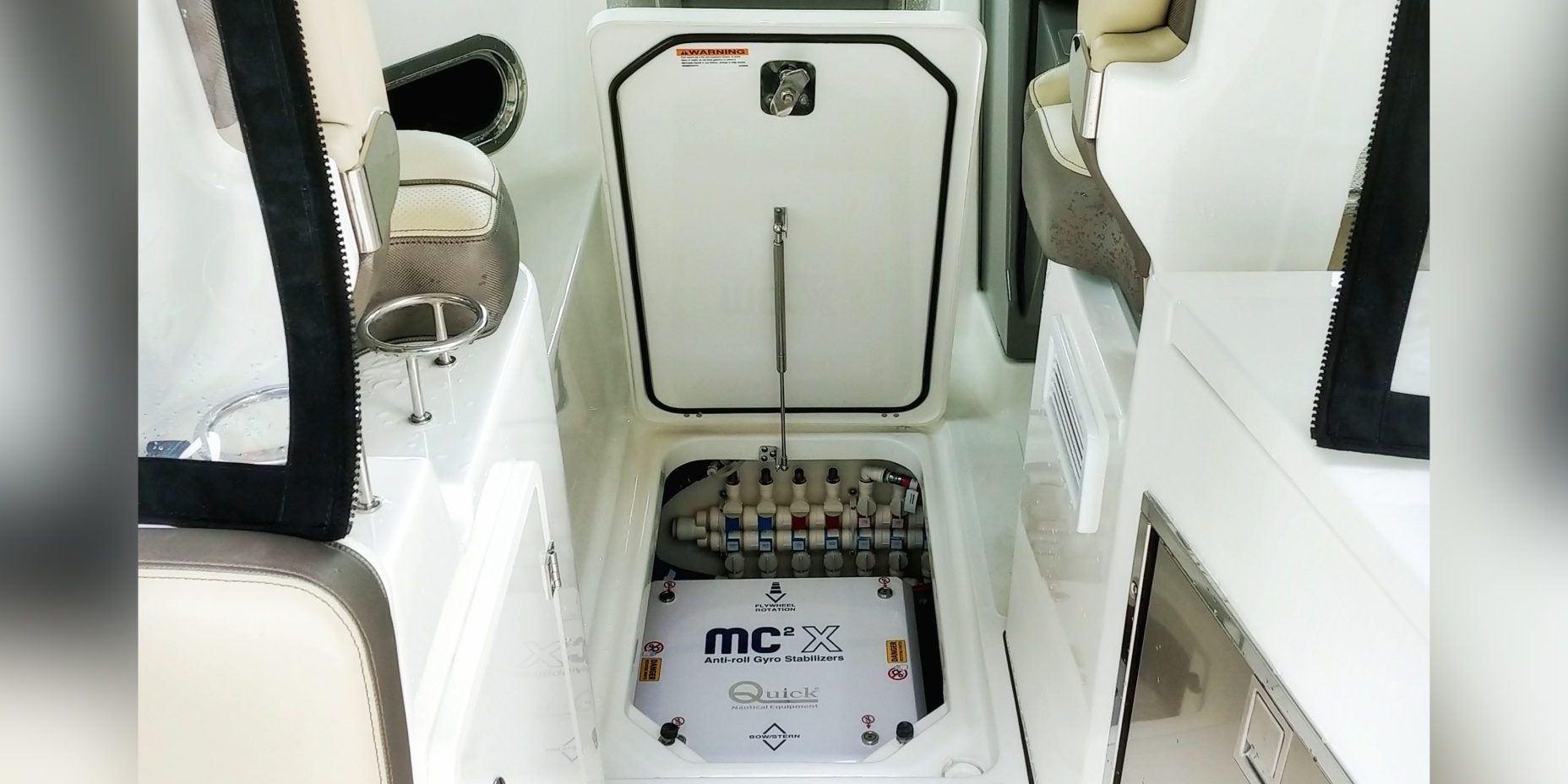
Our second Quick gyro stabilizer installation here in Singapore is on a dual console fishing boat with outboard engines. This is the first fishing boat in Singapore that has installed our Quick gyro stabilizer.
The installation took about a week, much longer than our previous one. The reason is simple – space. This boat required cutting, re-location of a water tank and removal of the water heater to accommodate our MC2X 7K. Yes, it’s a painful process, but the results are worth it. Here’s the details of the entire process:
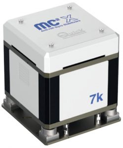
Gyro stabilizer details
Brand: Quick SpA
Model: MC2X 7K
Key specs:
– For boats weighing up to 10T
– 6678Nm output torque
– Weight: 300kg
– Size: 48 x 48 x 58.5cm
– Power absorbed: 1.5kW max
– AC input voltage: 90-260Vac
Boat details:
Builder: Pursuit
Model: DC 325
Build year: 2018
Full load displacement: Approx. 6.8T
Length overall (LOA): 10.52m
Waterline length (LWL): 9.32m
Beam overall (BOA): 3.3m
Max waterline beam (BWL max): 3.2m
Hull type: Round bilge
Hull construction: Fibreglass
Generator: 4kW, 220Vac/50Hz

Boat overview:
The boat has practically no space for our gyro stabilizer unless something is removed. The only spot that can fit our MC2X 7K gyro stabilizer is where the water heater was located. The owner decided to sacrifice his water heater because he reckoned that it is unnecessary to have a water heater in our Asian climate.
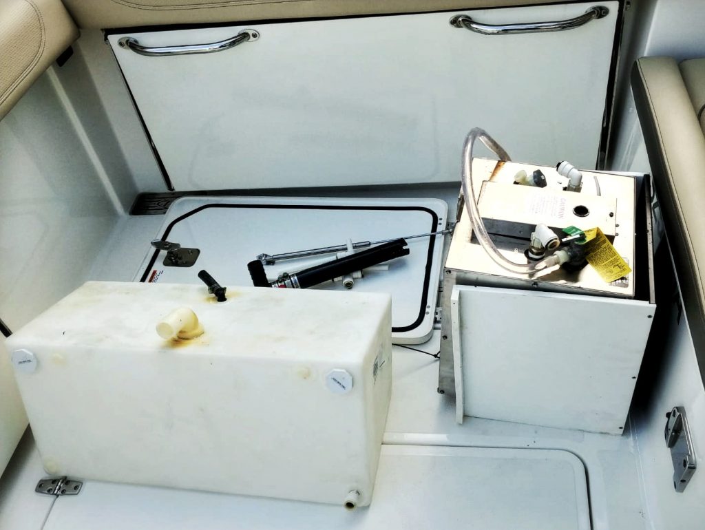
The water heater is located mid-ship of the boat – the ideal location for our gyro stabilizer. The water heater (the black box) is shown below.
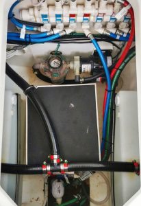

From the photo above, you would also have noticed that the water heater is sitting in between 2 water tanks. The starboard water tank had to relocated to the bow compartment in order for the gyro stabilizer to go in.
Even with the water heater removed & the water tank relocated, the opening still needed to be cut because the width of the gyro stabilizer is about 4.5cm longer than the opening’s width.
Thankfully, the boat owner is agreeable to this massive “surgery” as he calls it. Haha. As suppliers, our hope is that this will be the most complicated gyro stabilizer installation we will ever undertake XD
With the agreement in place, it was time to start work.
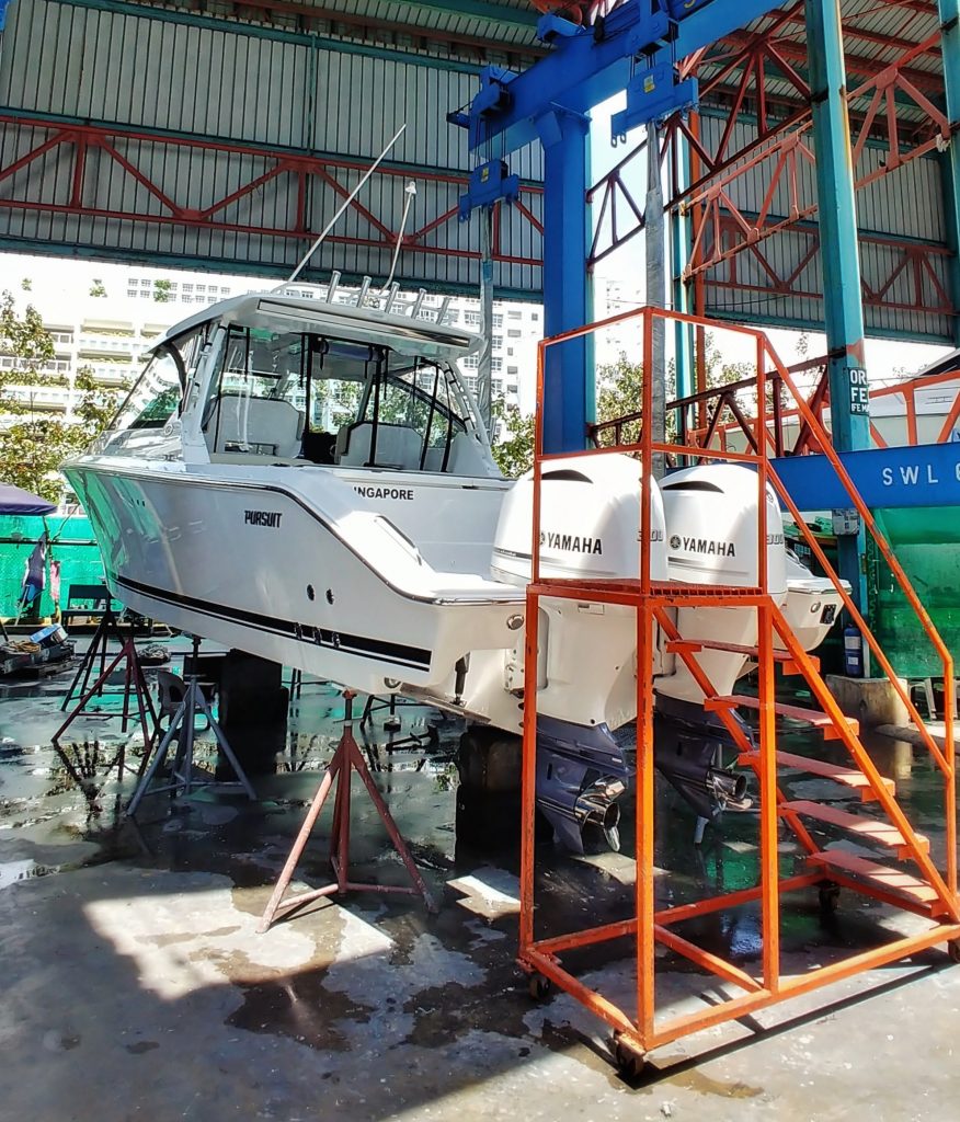
Pursuit DC 325 hoisted up in the yard for our Quick MC2X 7K gyro stabilizer installation
Installation step 1: Vacating the area for the gyro stabilizer entry
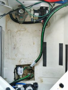
Starboard water tank (left of photo below) and water heater (right of photo below) removed. Compartment vacated.
Installation step 2: Building the base for the gyro stabilizer
This is always the MOST IMPORTANT step for every gyro stabilizer installation.
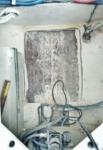
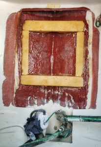
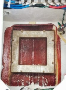
The base is made of an aluminium alloy that is glassed onto the fibreglass hull. The above photos shows the transition of the installation base area. From left to right – levelling of the base, laying of Polyurethane (PU) foam to compensate for the voids and lastly, laying on the aluminium alloy base plate that the stabilizer will be bolted on.
Installation step 3: Cutting of the hatch & lowering the gyro stabilizer into place
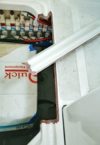

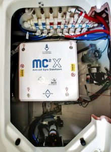
Installation step 4: Installing & wiring the driver & touch screen control
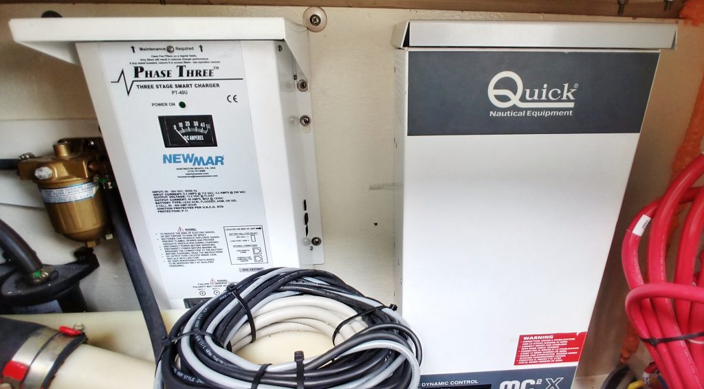
Installation location of our MC2X 7K driver
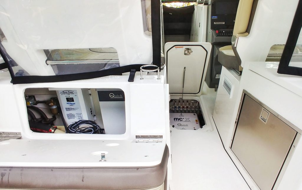
MC2X 7K driver installation location on deck view

Cutting a hole on the dashboard to fit our gyro stabilizer 5-inch control panel
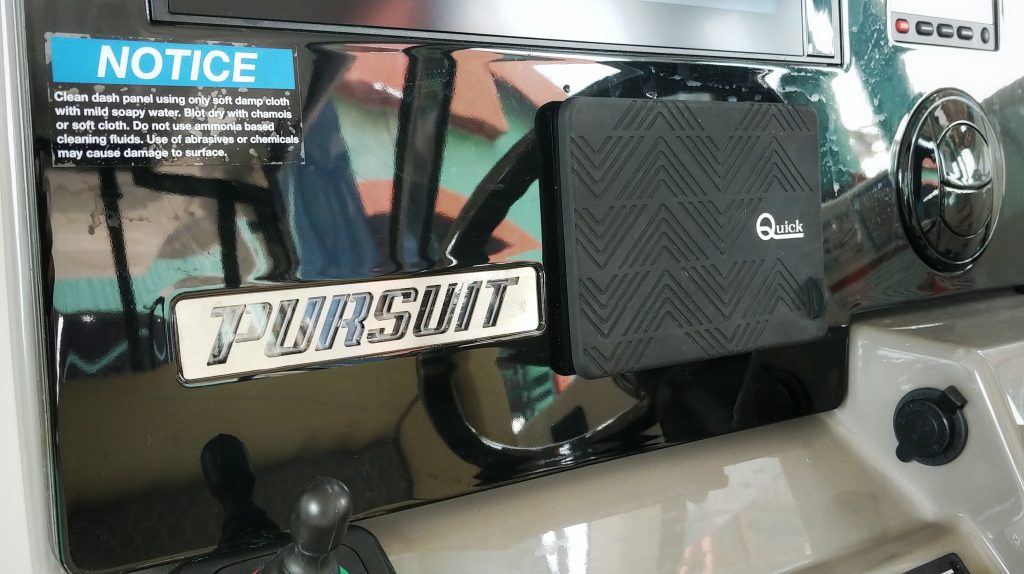
Installation of our touch screen control panel complete
Installation step 5: Glassing back the hatch

The hatch is glassed back
Installation is complete!
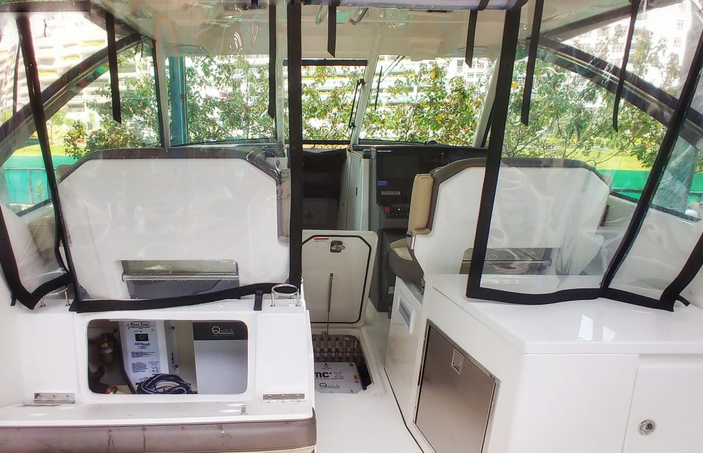
All done! MC2X 7K on our client’s Pursuit DC 325!
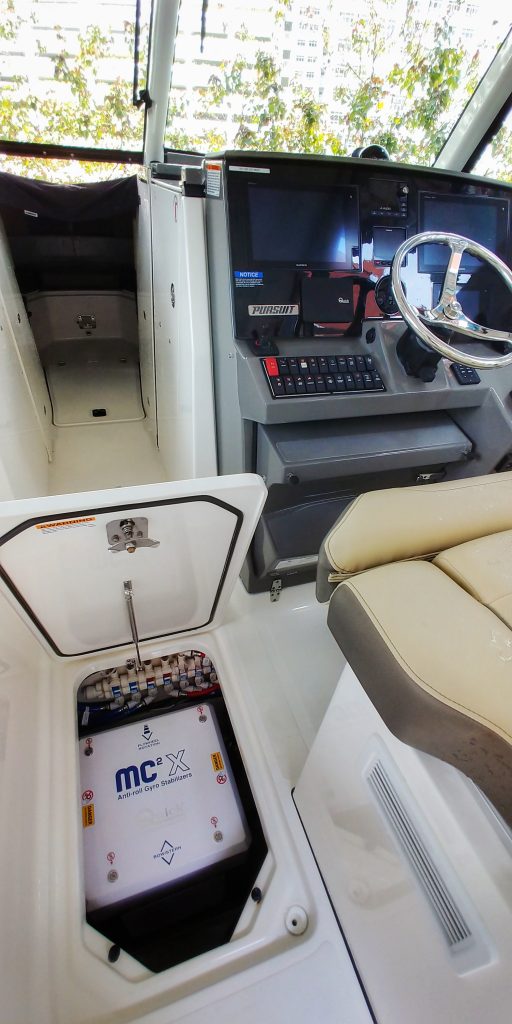
MC2X 7K right beside the wheelhouse
During the commissioning we did a rock-the-boat test and client was happy with the results! Stay tuned for our sea trial results!


